Features
Research
Strategies & Innovations
Slotted wells over bedrock
Tips for making screens that will not impede good flow
January 9, 2017 By Ken Hugo
Scientific studies and literature from various manufacturers provide numerous discussions and procedures for installing screened wells over unconsolidated sands and gravels. These calculations usually are concerned with preventing the migration of fine sediments in the water during pumping.
Less consideration has been given to slotted screens placed over consolidated formations where the screen is cut on the site. Usually it is done properly and is not much of an issue. Let’s consider some factors of the design to make sure that what we are doing we are doing well.
Slot width
Slotting is typically done with the aid of a circular saw, but does slot width matter? A recent review paper in Hydrogeology Journal (“Review: Hydraulics of water wells – head losses of individual components,” Houben, G.J. Vol. 23, pp. 1659-1675, 2015) shows that very small slots can have some effect by restricting flow. Slot widths of less than 0.3 millimetres can have an adverse effect. This width corresponds to 0.01 inches, or the more commonly stated 010 slot size, much finer than can be made with a circular saw. Even this slot size makes a difference only in highly permeable formations and has no effect in low-permeability zones.
A very fine slot size such as 010 can make development of the well difficult. So the finest slot size (010) should be avoided in high-volume wells, but the more commonly available 020 or higher slot size will make no appreciable difference.
Slot orientation
Slots are sometimes cut on the diagonal. However, the collapse strength of the pipe should be considered, as it will be more adversely affected by diagonal slots than vertical slots.
Number of slots
One is tempted to make as many slots as possible to increase the amount of open area, but too many slots will compromise the strength of the screen. The number and width of slots, along with the screen diameter, will control the entrance velocity of water into a well. A frequent rule of thumb is that the entrance velocity should not exceed 0.03 metres per second (0.1 feet per second), although this value appears to be more related to corrosion than restriction of flow.
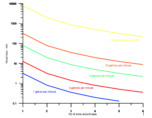
Houben found that flow velocities much higher than this, up to 0.5 metres per second (1.6 feet per second), will have no significant effect on head losses due to water flowing through the screened zone. The entrance velocity is a function of the pumping rate, the length of screen, the radius of the well, and the number and width of the slots. Using equations taken from the above mentioned article, for a typical 4½ diameter pipe and slot widths of 3 mm, the graph graph pictured below shows the head loss per metre of screen with the number of slots and pumping rate. A well that produces 10 gallons per minute per metre of aquifer will have head losses of less than 0.3 m if only one slot is used. For a typical well that has three to four slots around the circumference head losses of less than 0.1 m are calculated. All the graph lines flatten out and it is of limited use to put more than four or five slots around each section of pipe.
Diameter of well
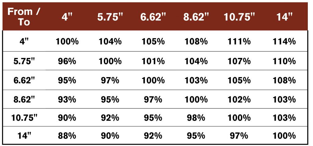
Increasing the diameter of the well will allow for a higher pumping rate from the well, but the effect is limited. This is because the pumping rate is expressed as a log term with respect to the well-bore radius. As an example, consider the following table, which shows the increase (or decrease) in flow rate due to a change in well radius. The table can be read to show that increasing the well diameter from 6.62 to 10.75 inches results in only a five per cent increase in well productivity.
If you choose a larger diameter of well for other reasons (principally pump size), you may not see a great change in well productivity. (See chart)
Length of screen
One can place a screen over the entire length of an unconfined aquifer, but because pumping will result in some drawdown around the well, there is no point in having a screen over the drawdown portion. However, too short a screen will result in a less efficient well. The recommended practice is to balance the two factors.
Hydraulic calculations show that 85 per cent of the available yield occurs when about 65 per cent of the available drawdown is used. As a result, it is general practice to screen the lower third of the aquifer. It should also be noted that many regulators do not want to see the pump placed below the top of the screen, so placing the screen at the top of an unconfined aquifer would result in no available drawdown and, therefore, no allowable pumping.
In a confined aquifer, maximum pumping rates are achieved when the entire aquifer is screened over, and efforts should be made to screen as much of the aquifer as possible. A screened zone that is too long may result in multiple aquifer completions. This situation should be avoided, as the multiple aquifer completion can result in flow from one aquifer to the other within the well or possibly the mixing of two zones of different water quality.
Effect of encrustation
The long-term well life should also be considered. Some wells are susceptible to encrustation by chemical (that is, calcium carbonate) or biological means (that is, iron bacteria). Although a completed zone with only a few thin slots may not affect flow rate at the time of completion, remember that this well situation may change. Allowance for extra slots may be advisable to maintain the productivity of the well longer should encrustation occur.
Ken Hugo is a technical director and hydrogeologist with Groundwater Information Technologies (GRIT).
Print this page