Features
Pumps
Submersible motor designs – How their difference impacts pumping operations
April 29, 2022 By Jeff Frank
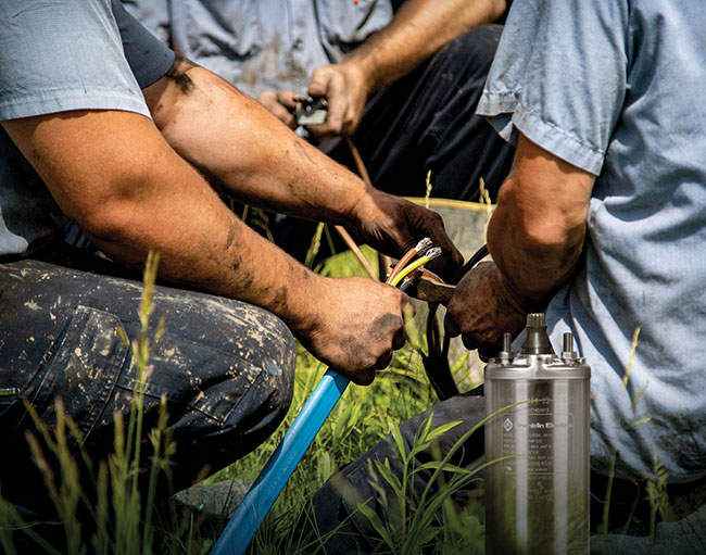 Preparing to install a submersible motor design. Photo credit: Franklin Electric
 No pumping system is complete without the right motor. It not only drives the pump, but it must also safely and reliably take the static and dynamic loads from the hydraulic stresses of the entire system.
No matter how many motors water professionals have selected and serviced over the course of their career, every pumping job is different – and every application requires different considerations in terms of overall efficiency, reliability, and robustness. This is often where submersible motors stand apart, delivering benefits for pump operators in charge of potable water and irrigation systems, construction sites, mine dewatering among other applications.
What components are part of a submersible motor design?
Submersible motors feature a variety of engineering considerations that set them apart from their surface-mounted counterparts. Because drilling and well construction costs increase dramatically with borehole diameter, submersible pumps and motors are characterized by their slender construction. But appearance is just the beginning of the performance and operational benefits submersible pump systems deliver:
Electrical designs: induction motors & permanent magnet technology
Not all electrical submersible motors use the same design, and there are several different technologies to choose from, including induction and permanent magnet (PM).
Induction motors have often been considered the workhorse of submersible systems. They often feature a squirrel cage design since there are no electrical connections between the rotor and stator that need to be kept watertight. Additionally, induction motors of this type can be repeatedly produced to ensure high quality and low cost versus other motor designs, making them an accessible solution for pumping system owners and operators.
Since the motor is induction driven, the rotor turns at less than synchronous speed, which is why this motor type is often referred to as an asynchronous motor. This speed differential is defined as slip. Due to the rotor slip and the shape of the motor’s torque-speed characteristic curve, the motor has very stable operating characteristics, even under short overload and peak load conditions that make it an ideal driver.
When properly selected, the squirrel cage induction motor can easily meet the load demands of a centrifugal pump. However, when used in a standard pressure regulated water system, controlled by a pressure switch and bladder tank, it is best to limit the frequency of motor starts with approximately one minute between consecutive starts to ensure adequate cooling.
PM motors are growing in popularity in submersible applications. Unlike an induction motor where the internal rotor is an electromagnet and becomes energized by the system’s power supply, PM rotors are always magnetized due to the raw material selection.
These internal magnetic rotors make them more efficient, especially at reduced speeds and partial loads. The inclusion of the rare earth magnet rotor removes the slip factor seen in an induction-style motor. This creates the opportunity to achieve full synchronous rotational speeds in cases where that provides an operational benefit. Another way to view this is that lower input power is required for an equivalent output power produced by an induction design motor — saving on operational costs every time the motor runs. Also, lower current means that specific components of the system — including variable frequency drives, motor cables and filters — might result in smaller size requirements and, consequently, become less costly.
Bearing system
The thrust bearing system handles the static and dynamic axial forces generated by the static and dynamic power needed to pump the water. Depending on the pump’s operation point, the axial shaft force direction can be either towards the motor (downthrust or thrust) or in the opposite direction (upthrust). At start-up, while the pump is still building initial backpressure, the upthrust bearing prevents upward movement of the rotor.
To handle downthrust during normal operation, a strong, reliable Kingsbury-type thrust bearing carries the load. Based on field experience, the Kingsbury-type thrust bearing is the best solution to fulfil the critical function of thrust load handling due to its high capacity and self-aligning properties. The total load capacities of any specific motor design can vary depending on the motor ratings.
Thrust and radial sleeve bearings are water lubricated. Stainless-steel sleeves in combination with carbon-graphite are often the best choice since the carbon-graphite combines carbon’s strength, hardness, and wear resistance with graphite’s corrosion resistance and self-lubricating properties. While running under water, each of these bearings generates a low-friction film on their smooth surfaces to provide maximum protection through this hydrodynamic seal. Once hydrodynamically separated, the bearing is fully lubricated and can operate continuously in this condition. This means the lifetime of the bearing system is unlimited if external influences such as water hammering, vibration and sand entry can be avoided.
Shaft seal
The shaft sealing system is made of a sand slinger and a fixed, mechanical or lip-style seal. Lip seals are normally supplied as standard. For severe applications in areas with fine abrasives or sand, Silicon-Carbide (SiC) mechanical seals are recommended.
Stator design options
Two different motor stator designs are available within the submersible motor world:
- Dry or encapsulated motors
- Wet-wound or rewindable motors
The stator of an encapsulated motor is wound with the same magnet wire used in all standard industrial motors. A stainless-steel shell on the outside and a stainless-steel liner inside are welded to end rings at either end of the stator to seal the winding from the outside environment.
No fluid, either from inside the motor or from the well, can enter the windings. The winding area is then filled with a special encapsulation resin that provides mechanical stability and promotes heat transfer to the outside of the motor. In some cases, the special resin also provides slight protection against voltage surges due to its dielectric properties.
The stator of the wet-wound or rewindable motor is wound with an electrically insulated magnet wire. The wire insulation is polyvinyl chloride (PVC) or polyethylene (PE). The internal liquid fill solution is directly in contact with the wire. In addition to the magnet wire insulation, all internal electrical connections must be isolated to prevent motor grounding.
NEMA standards
The North American NEMA (National Electrical Manufacturers Association) standards are accepted as the global benchmark for the pump mounting dimensions of four-, six-, and eight-inch submersible motors. No industry standards exist for larger diameter motors. The NEMA standards specify the flange and splined shaft dimensions of the motors.
How do the different stator designs compare?
Electromagnetic differences
A fundamental difference between the rewindable and encapsulated motors is in the actual amount of current-carrying copper that can be placed in the motor stator slots. The wire insulation used to build rewindable submersible motors varies considerably from the magnet wire insulation used in encapsulated motors: 0.35 to 0.5 mm/side compared to 0.04 mm/side, respectively.
This means the encapsulated motor can carry more electrical current while running at higher wire temperatures since there is no wire insulation to be damaged by these temperatures. Overall, this allows for encapsulated motors to operate at greater energy efficiency ratings. On the other hand, rewindable motors built with stator winding wire that is PVC coated must maintain a lower operating temperature to not damage the insulation, and ultimately the motor’s ability to operate.
The thicker the wire diameter (copper plus insulation) means that less copper is available for power generation. To compensate for this reduced copper volume, rewindable motors will be made longer in many cases. This design helps provide equal power output to the encapsulated submersible motor. To demonstrate this, compare the six-inch diameter, 20 HP, rewindable and encapsulated motor lengths, where the rewindable motor must be 25 per cent longer than the encapsulated motor to provide the same power output.
Thermal characterization of encapsulated motors vs. rewindable motors
As briefly mentioned previously, the most notable difference between encapsulated and rewindable motors is the allowable winding temperature rise. In general, the allowable winding temperature rise for a rewindable motor must be less than the encapsulated motor. For this reason, rewindable motors must run at a temperature closer to the ambient fluid temperature. This also means that encapsulated motors allow for a greater application temperature rise margin before reaching the point of permanent damage.
The lower temperature rise of the rewindable motor does not mean that it is more thermally robust. In fact, the encapsulated motor has a wider temperature operating range, making it more thermally robust, and less likely that it would need to be derated in a higher ambient water temperature.
As a motor application is analyzed — comparing the water ambient temperature, the allowable winding rise, and the motor’s power output rating — there is generally a linear relationship that can be maintained with respect to the amount of efficiency and performance loss in the system.
Another case when a wider operational temperature margin becomes an advantage is during short-time current overloads, such as at locked-rotor or during an electrical line start. The extra energy is stored in the copper winding as heat. Under these conditions, the amount of heat is measured as a temperature rate-of-rise, and it is proportional to the square of the current density in the copper. Using this, the winding temperature rise can be calculated for each motor type. Under a full voltage, locked-rotor condition, the encapsulated winding heats up at the rate of 19 degrees Celsius/second while the rewindable winding rises at 31 degrees Celsius/second.
Under normal operating conditions, submersible motors and pumps have inherently low internal inertial losses and start very quickly, so the temperature rise during starting is quite acceptable. However, if the motors are not able to accelerate for some reason, the rewindable motor will tend to be more fragile than the encapsulated motor. This is because the rewindable motor has both a lower allowable insulation temperature and a relatively higher rate-of-rise of temperature.
Despite these differences, it is important to remember that over-heating is the main cause of failure in many applications of submersible motors — so, regardless of construction type, it is recommended to protect both encapsulated and rewindable motors with “quick trip” (must trip within 10 seconds @ 500 per cent IN) overload protection.
Ability to repair/maintain encapsulated motors vs. rewindable motors
When a motor fails, it’s important to quickly determine the cause. If the failure is for reasons related to misapplication or improper installation, all installation deficiencies must be corrected before another motor is installed. Both motor types are repairable and spare parts are often readily available.
The modular concept divides the motor into its main parts: stator, rotor, upper and lower end bell, seals, and bearings. The reliable and proven mechanical parts, end bells, seals, and bearings are interchangeable for both designs. When the failure mode is that of a failed stator, the encapsulated motor’s stator may be replaced or the rewindable motor may be rewound.
An encapsulated motor can be repaired quickly with a factory original stator. This results in no change in motor performance since each stator is wound using the same raw materials, automated winding lines, and manufacturing processes.
The rewindable motor is easy to rewind in the field. The ends of the 18-slot stator are open to allow easy removal, reinstallation, and forming of the winding coils. The motors are wound with PVC wire, which is widely available, and the winding data is published. It is important to repair the motor in accordance with factory specifications for materials and winding data. Failure to do so will result in altered motor performance. Repair kits that contain pre-wound coils, slot insulation, and cable splicing materials are available from the factory should you or the repair shop prefer to use factory components.
Conclusion
Selecting the best motor to power your submersible pump is a critical consideration to your overall operations. Your motor’s long-term performance – and the performance of your pumping system – relies heavily on having the right configuration for your site and your needs. This is what makes submersible motors a smart choice in many applications. They are more advanced than ever in terms of features and overall operation and offer highly efficient performance.
Jeff Frank is global product manager at Franklin Electric. He is a mechanical engineer with 15 years’ experience in the water systems industry. He has helped Franklin transition from an OEM component supplier to a holistic water systems pump manufacturer and reseller.
Print this page